
Physics 2212, Sim 12: Inductance and RL Circuits
Eric Murray, Summer 2020
Question these experiments will enable you to answer: What is the time constant of your simulated RL circuit?
Features: The simulated circuit consists of a battery, switch, resistor, and inductor in series. A voltmeter measures the potential across the inductor. Fitting a linear curve to the appropriate function of this potential as it depends on time, enables the time constant of the circuit, and therefore the inductance of the inductor, to be calculated.
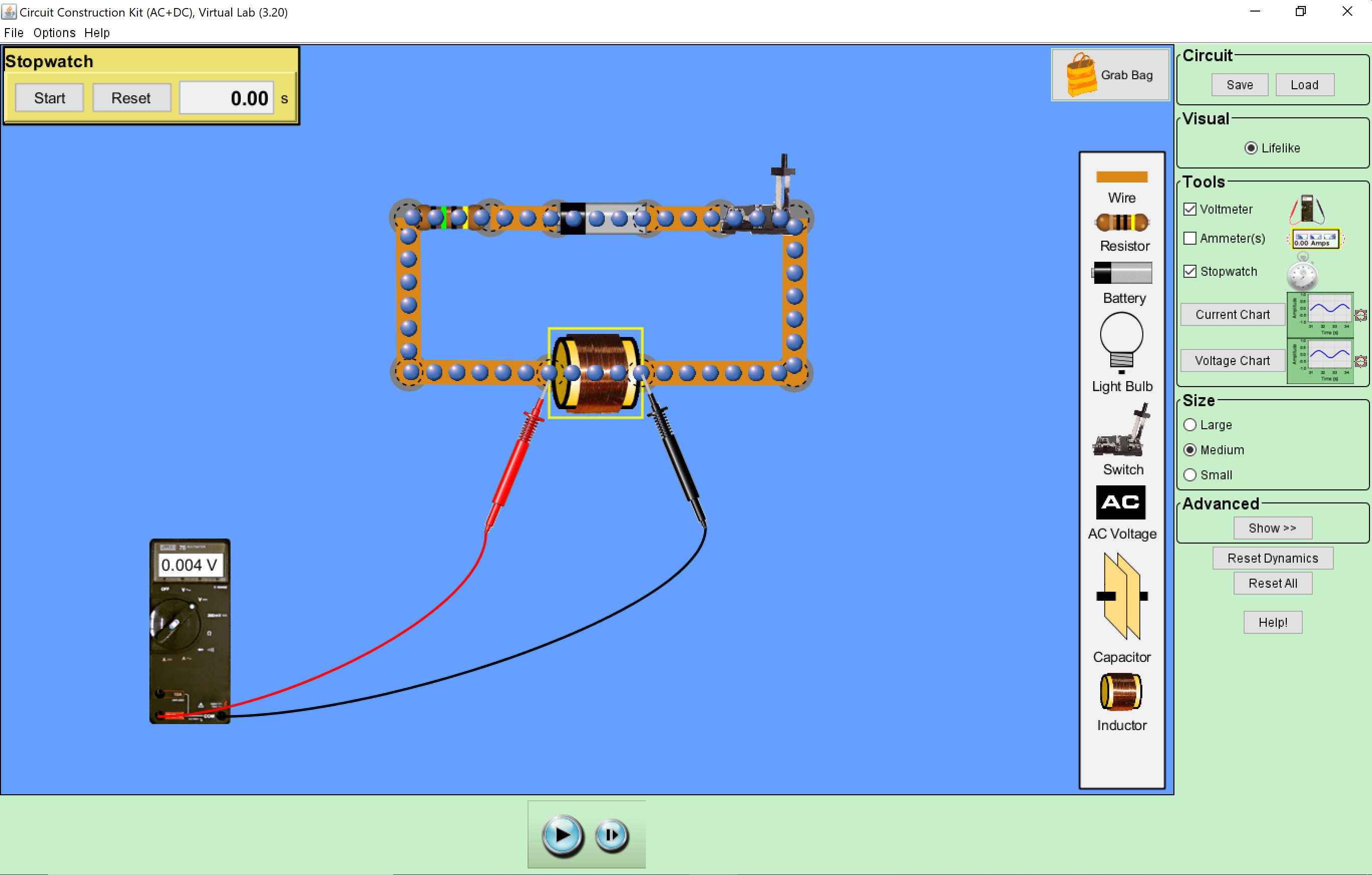
Preliminaries: Open Circuit Construction Kit (AC+DC), Virtual Lab (Java required). Build a simulated series RL circuit, including a switch. Use a voltmeter to measure the potential across the inductor. There are many valid ways to build this circuit, but an example is illustrated (and linked to a larger image). Set the battery emf, inductance, and resistance to 50 V, 100 H, and 5 Ω, respectively. Enable the stopwatch.
Experiment 1: Pause (❘❘) the simulation, start the stopwatch, close the switch. Play (▶) the simulation, then pause it immediately. Record the time and the potential across the inductor. Note that the stopwatch keeps simulation time
, not real
time.
Repeatedly Play and Pause the simulation to record measurements approximately every second for 10 seconds. Then record measurements approximately every two seconds for the next 10 seconds. Finally, record measurements approximately every five seconds for the next 40 seconds.
Calculate a theoretical value for the inductor potential at time t = 0. Calculate -ln(ΔVL/ΔVL0) for each measurement. As seen in the prelab, this should be a linear function of time. Confirm this with a graph. Use linear regression to determine the slope and its uncertainty. From that slope, calculate the time constant of your circuit. Knowing the resistance of your resistor, calculate the inductance of your inductor.
Summary: Review your worksheet. Think about the goals of these experiments, your results, and expectations from while writing your discussion.