 The magnetic force, F, on a current-carrying wire
Edward Thomas, Summer 1999
revised by Eric Murray, Fall 2006
You may wish to review the Error Analysis portion of the Prelab for Physics 2212 Lab #8, Capacitance and RC Circuits.
 The magnetic force, F, on a current-carrying wire
F = IL×B or F = ILB sinθ
depends on the current through the wire, I, the length of wire in the magnetic field, L, the magnitude of the magnetic field, B, and, since L and B are vectors, the angle θ between the length of wire and the field. The accompanying illustration of this relationship is a perspective sketch — note that L and B define a plane, and F must be perpendicular to that plane. The direction of (conventional) current defines the direction of positive L.
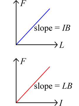
 This relationship will be examined two ways. First, a constant current will be selected, and
wires of various lengths will be placed perpendicular to a magnetic field (θ = 90°).
The force magnitude will be measured. A graph of the force as a function of length should yield a straight
line of slope IB. Since I is known, the magnitude of the magnetic field can be calculated.
Next, a particular wire length will be selected and placed perpendicular to a magnetic field (θ = 90°). Various currents will be passed through the wire, and the resulting force magnitude will be measured. A graph of the force as a function of current should yield a straight line of slope LB. Since L is known, the magnitude of the magnetic field can be calculated.
These two measures of the magnetic field magnitude can be compared to each other.
Experimental Technique: An obvious way to do this experiment is to put a wire into the field of a permanent magnet, pass current through the wire and measure the force on the wire. Then one can vary the length, the current and the angle to check out everything in the law. There are two problems with this. First its difficult to measure a force on a rigid wire (there will be current leads and other stuff hanging on it which confuses matters). Secondly the leads connected to the sample wire might also experience part of the magnetic field and this produces forces which may confuse matters. The experiments we have designed for you overcome both of these things easily.
Measuring the Force: Consider first figure above; the force is on the wire which in this case is up. Let us assume that the magnetic field is produced by a horseshoe magnet. Newton's Third Law tells us there must be an equal an opposite force downward on the magnet. Instead of measuring the force on the wire, we could just as well measure the force on the magnet. This is what we do by placing the magnet on the pan of a scale and measuring force as an apparent weight.
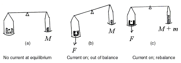
An equal arm balance is illustrated below. Initially the magnet is placed on the pan and a mass M added to the other pan to restore equilibrium. Obviously M would be the mass of the magnet and the force of gravity on the magnet would be its weight, Mg. The wire is in the jaws of the magnet and suspended rigidly from a stand which sits on the bench (it does not touch the magnet or scale).

Now we send current through the wire. There will be a force F on the wire (let us assume up) and therefore a force of reaction on the magnet (down) causing the magnet pan to go down, just as though additional mass had been placed on that pan. We now add additional mass m to the mass pan and restore equilibrium. The gravitational force on the additional mass m is mg, and that exactly equals the force on the magnet which in turn is exactly equal to the force on the wire. Thus
F = mg = ILB sinθ
and we have our measurement of the force on the wire.
(Of course if the direction of the current in the wire were reversed then the force on the wire would be down, the force on the magnet up, and to restore equilibrium a mass m would need to be subtracted from the mass scale pan. That is an equally good way of doing things.)
The balance we use in the lab is not actually an equal arm
balance where
masses need to be added or subtracted. Rather it is a variable arm type of balance where a
mass rider is moved along the mass arm
until the torque on the mass arm
(clockwise) balances the torque on the scale arm (counterclockwise). The variable arm has a
calibrated scale marked on it so that the position of the rider tells you the actual
mass on the scale pan.
 Wire Samples:
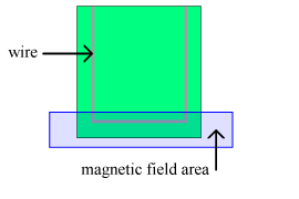
These are made of a wide strip of metal deposited in the shape of a rectangular
U
on an insulating board (in fact a Printed Circuit or PC board). This is
placed in the magnetic field, as shown, so that the connecting central leg of the
U
is entirely in the field. It is on this piece of the wire that we wish to
measure force and the force will be either up or down (depending on the current
direction).
What about forces on the legs
to the left and right which act as
leads to convey the current to the wire? These legs will be partly in the magnetic
field and experience some force. Make sure you can think of at least one reason why
they do not matter.
The wires are wide (about two mm). Think about whether you should measure the outer length (to outside the legs), the inner length (to inside of the legs), or something else.